
I have begun construction of a sculptured rocker, based on the design of Sam Maloof. This will be a work in progress. I will make updates from time to time as I proceed.The inspiration (and instruction) for this project comes from Woodguy1975. He has offered a class to learn how to make a rocker like this, and the pics that follow document my construction progress.
This is not intended to be a comprehensive tutorial, just an overview to help understand some of the major steps involved.
DESIGN & TEMPLATES
 The first steps involve taking careful body measurements to determine the dimensions for the rocker. The major dimensions (including the size of the seat and the height of the back and arms) are all custom tailored for the individual intended for the chair. Once these dimension are established, the main template is created.
This is a process of trial and error, using layout tools and lots of erasers to come up with a design.
Mine was not very creative. The idea is to figure out exactly how you want your chair to look overall, and make a master template like this one. Once the master template is made, it can be used to transfer dimensions to make other working templates and finally to shape the stock.


Some of the working templates are shown in the second picture, including the seat template and the front/back leg templates. Creating the seat template requires a series of precise layout lines and measurements. Any mistake here could result in serious problems later.

My chair will be made out of walnut. I used all 8/4 stock, about 80 bd ft total. Two of the pieces had to be at least 7″ wide to make the back leg.
All the stock was dimensioned and planed, and some of it was re-sawn to make the laminations for the rockers.
All the stock was dimensioned and planed, and some of it was re-sawn to make the laminations for the rockers.
ROUGH-SHAPING THE SEAT
My seat is made up of five boards which are wide enough to provide space for the seat template. Before gluing up the seat panel, some of the initial rough shaping can be done on the band saw. The inner contour of the seat template is traced onto the boards; a separate template is created for the front profile of the seat. These lines are used as a guide for the initial band saw shaping of the seat.


Once the contour of the seat is marked on the top & front of the seat boards, the initial shaping is done on the band saw. The panel is separated and the layout lines are transferred by eye onto the inside of each of the seat boards. Each board is then taken to the band saw, and cut out close to the layout lines.


At the band saw, each piece is fed through free-hand, using the layout lines as a guide. This is kind of tricky. It should be noted that this is not a safe band saw technique, and it is not recommended! Since the feed direction changes, a fence cannot be used. Establishing the proper angle to start the cut is also tricky, since you can’t see the guide line on the end of the piece.
 To help with this, I set up a mirror so I could see the line on the end. This helped me to establish the proper angle from the start, but doesn’t really help beyond that.
The guide lines were intentionally drawn with a dull pencil, giving 1/8″ or so margin for error during this phase. With this in mind, I tried to saw just on the inside of the line, although in some places I did cut right on the line.
In order to do this kind of cut (relatively) safely on the band saw, the wood has to be positioned with the “inside” guide line down toward the table where it can’t be seen. The wood has to be held at a constant angle to avoid cutting through that line on the bottom.

SEAT & LEG JOINERY
Once the seat is roughed out, and while the sides are still square, the next step is the joinery between the seat and the legs. This is extremely important not only for strength, but also for aesthetics. The design of this chair really showcases the joinery, so any imperfections or gaps will be very visible.
This involved using a dado set on the table saw, and a rabbetting bit on the hand-held router. In order to achieve a perfect fit, the roundover on the insides of the legs (a 5/8″ radius roundover) must exactly match the radius of the rabbetting bit (ie, you need to use a 1¼” diameter rabbetting bit) .
This shows the joinery detail for the front legs. If the width of the leg is perfect, the bits match perfectly, and the dado depth was perfect, you can achieve a nice flush fit all around:


Here is the joinery detail for the back legs. Here, a precise fit requires a perfectly square notch in the back of the seat, and precise dado depth and matching bit profiles:


Once the joinery is all complete, the chair can be partially assembled for the first time:


It finally starts to take shape!
SHAPING THE BACK LEGS
The back legs are initially cut to rough shape on the band saw, using lines transferred from the back leg template as a guide. I then used the template as a pattern to refine the shape of the legs on the router table. Note: this method deviates from Woodguy’s class – he uses a grinder to do this shaping. I figured since I spent so much time “perfecting” the curves on the template, why not use it to shape the legs?


The template is attached to one of the legs using double-stick tape, being very careful to line up the front face of the template correctly with the flat surfaces on the front of the leg. These flat surfaces are the location of the joinery with the seat and the arms, so obviously any mistake here could lead to serious trouble later. The leg can then be shaped with a pattern bit on the router table.
The template is not used to shape the second leg; instead, the shaped leg is used as a pattern to shape the rough leg. The reason for this is so the seat and arm joinery will line up perfectly on both legs. A couple of pieces of 3/4″ MDF can be placed in the dadoes to “lock” the two legs together, with a little piece of carpet tape out at the top and bottom ends of the legs to keep them from swinging around.


 The only “gotcha” is to make sure the bearing is set high enough to clear the dado gap on the back of the legs (see the last pic on right).
SHAPING THE SEAT
I used a 9/25 Pfeil carving gouge to carve out the rough shape of the seat. This part actually went a lot quicker than I thought it would – I probably only spent about 2-3 hours on this. The second half of the seat went about twice as fast as the first half, so I’m sure I could do this a lot faster now that I have a little experience.
The gouge had an amazing edge on it, and really carved through the walnut easily. I got it all done without picking up the mallet even once.

Once I got down close to finished depth, I checked my progress frequently using a straightedge, keeping an eye on the shape of the shadow cast on the seat surface:


 The seat is further shaped using the angle grinder. This is a messy process, best done outdoors. This is also not for the faint of heart!
Once the seat shape is close to final shape, the edges and bottom curves are smoothed using rasps, a gooseneck scraper, and sanders. It takes a fair amount of meticulous work to smooth out the whole surface to achieve nice, flowing curves with no high spots.
As I was finishing up the shaping, I couldn’t help myself — I put a little mineral spirits on the seat, just to get a little “sneak preview” of what it would look like when finished:

ARM JOINERY AND SCULPTING

An arm template is made, based on the dimensions laid out on the master template. The design of my arm template is based on what I have seen in books, and looking at Woodguy’s example. I modified it a little to hopefully add a little more arm support back at the elbow.
 Using the dimensions from the original master template, the arm stock is cut to size and fitted to the chairs temporarily using dowel joinery while the stock is all still square. The back legs are drilled using the drill press (pic at right), and the front legs are drilled by hand.
The arm stock itself can be drilled on the drill press for the bottom hole, but the back hole requires drilling by hand.
 Once the arm joinery is done, the arm stock can be roughed out at the band saw. Doing it this way employs the freehand band saw technique that Maloof uses.
This saves some grinding time, but it is quite tricky. It is not a safe band saw technique, and is not recommended.
 Further shaping is done using the angle grinder, being careful to avoid grinding those areas where the arm joins the front and back legs. These areas will be shaped later after the chair is assembled.
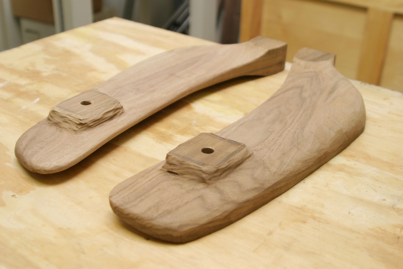
There is still some hand shaping to be done, but these pics show how the arms look after rough shaping with just the band saw and grinder.


SPINDLES
I wanted five spindles for my rocker, but started out making six spindles (including one “spare”). I chose a design that I believe is fairly “traditional”. The spindles are designed to fit the curve of the back perfectly, to make the chair as comfortable as possible.
The spindles are designed with the aid of a jig which helps to determine the curve you’re trying to fit.
Once that is done, a template is made and the spindles are rough cut on the band saw. The spindles are clamped together and the grinder and rasps are used to clean up the band saw marks and smooth the curves.
They are cut to final length on the table saw.


To keep the narrow part of the spindles straight and uniform, I set up the band saw with a tall fence and stop blocks:


The corners of the spindles are initially rounded over with the spokeshave. I put the spindles in place on the chair just to double-check how my design would look:


Final shaping of the spindles requires careful use of the saw rasp, patternmaker’s rasp, and spokeshaves. It was really fun learning to use these tools properly.
This took an entire day of work (with some work still left to do), but the result was well worth the effort:

CREST RAIL
A separate template is used to mark the design on the crest rail. The locations for the spindle holes are laid out just like on the seat. I decided to spread the spindles out a little toward the top, so I planned to cut out the insides of the back legs to give the spindles room to spread out. I drew these lines on the back legs, and then laid out the locations for the spindle holes accordingly:


The crest rail is drilled with the stock still square; the depth of each hole is determined by the bottom profile of the crest rail design. This, in turn, will ultimately determine the final length of each spindle.

After the crest rail is drilled, it is rough cut to shape, placed in proper position on the chair, and used as a guide to cut the spindles to length:


The crest rail joinery is then cut, using #20 biscuits to join the crest rail to the back legs. The crest rail shaping is done with the grinder and some rasps to get a fair curve. More shaping will be needed later, once the chair is assembled.


ROCKER LAMINATION

The rockers are bent laminations, made using a form with a specific curve to result in a good rocking motion. We used plastic resin glue. The initial glue-up creates the main curved portion, and the two smaller buildup laminations are added later.
 The whole assembly is then jointed and planed to make it square to the floor, with parallel sides. The tops are then flattened using the band saw and a hand plane, to create a flat surface to mount the chair on at a later date.
This lamination is ripped and planed down to make two identical 1¾” rockers.

I am in the process of trying to figure out how to build a rocking chair and am experimenting with rocker arc's? Having made up a rough template in the garage. What radius/arc did you use for your rocker. I would love to see your finished chair, particularly the shaping part. Do you know of any good books and where I can get some basic templates. Hope you finish it - it would be a shame not to see it thru.
ReplyDeleteRegards - Peter
Correct me if I'm wrong, but to figure the rocking angle, you take the leg length or distance from the top of the front of the seat to the ground and multiply by Pi or 3.14. Eg: 15" leg length would result in a 45" radius for the rocker arc.
ReplyDelete